JH JONATHAN HELMIN / ENGINEERING

ELECTRICAL ENGINEERING · UNIVERSITY AT BUFFALO

Engineering beyond
one discipline.

I’m Jonathan Helmin, an electrical engineering student with hands-on electrical trade experience. I build projects that connect electronics, mechanical design, and control.

Explore DUNCE ↓
CURRENT FEATURE

DUNCE MKII

A modular robotic arm.
Designed, assembled, and tested independently.
Inside the project ↗
BUFFALO, NYA GROWING BODY OF WORKSCROLL TO EXPLORE ↓

01 / FEATURED PROJECT

One platform.
Many engineering lessons.

Independent robotics project
Summer 2026

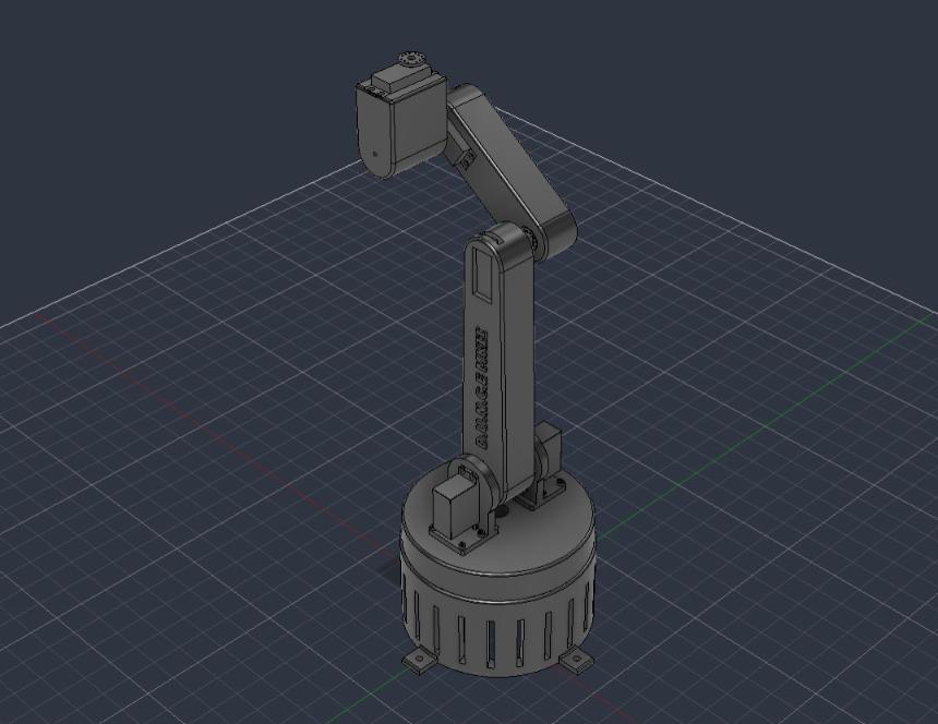
Autodesk Fusion model of the DUNCE MKII robotic arm
01 / DUNCE MKII · Autodesk Fusion model
INDEPENDENT PROJECT

DUNCE MKII

A five-degree-of-freedom robotic arm, controlled by two joysticks and built as a modular platform for experimentation.

I designed the mechanical components in Autodesk Fusion, developed the electrical systems, assembled the robot, and tested the final assembly.

Electrical designCAD & 3D printingMotor controlPrototyping
Explore the engineering decisions ↓
5 DOFFinal arm configuration
24 VSingle motor power source
270°Mechanical base rotation limit
ModularInterchangeable end effector interface

PROJECT PURPOSE

Learning across
disciplines.

I created DUNCE to turn my interest in electrical, mechanical, and software engineering into practical experience. With every iteration, I deliberately introduce a new engineering challenge so I can keep learning beyond what I already know. MKI focused on power and control systems; MKII pushed me into mechanical design through custom printed components, gear reductions, and a modular wrist. The goal is to understand how these disciplines work together by designing, building, testing, and refining a complete system.

SCOPE & OUTCOME

MKII met the goals for an interchangeable end effector, stepper motors and gear reductions, and a shared motor power source. I reduced the original six-DOF goal to five DOF to stay within budget and schedule.

ENGINEERING IN PRACTICE

Technical challenges
& design decisions.

The constraints, alternatives, and choices behind DUNCE MKII.

01 / WIRING

Protecting the wiring

Challenge. Base rotation could wrap wiring around the arm, risking damage, disconnection, and restricted movement. A slip ring and internal routing exceeded the project’s time and budget.

Decision. I limited base rotation to 270° and enclosed the wires in a protective sleeve.
02 / BASE JOINT

Reducing base friction

Challenge. Reduce friction at the base joint with a simple, inexpensive solution. I considered lower-friction material and lubrication.

Decision. An integrated raceway with loose stainless-steel balls offered a simple, inexpensive solution using materials I already owned.

03 / MODULARITY

Designing for interchangeability

Tradeoff. A permanently attached end effector could offer more rigidity, but would limit future prototyping.

Decision. I chose a modular wrist interface so I could develop and test different end effectors without redesigning the rest of the arm.

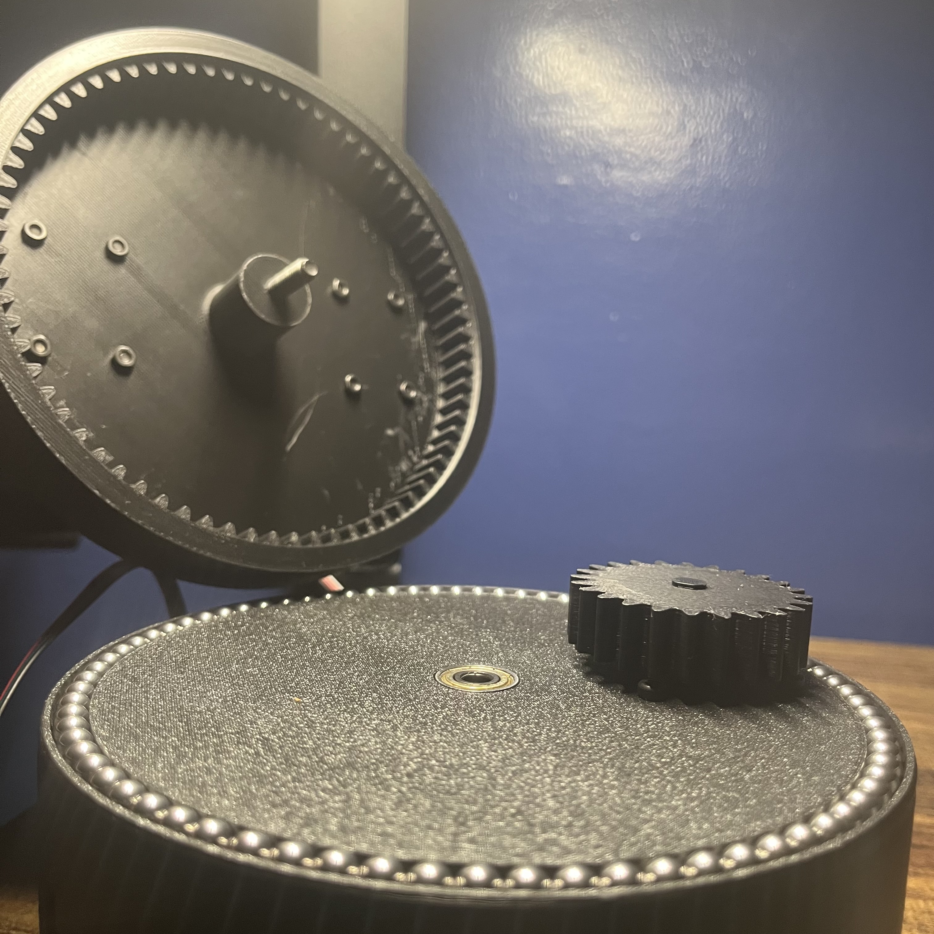
DUNCE base joint opened to show the internal ring gear in the lifted lid, the spur gear, and the stainless-steel balls around the base raceway
03 / Base joint and lid separated · Internal ring gear, spur gear, and stainless-steel ball raceway

DESIGN DETAIL / THE BASE JOINT

A closer look
at the mechanism.

With the base lid separated, the internal ring gear, spur gear, and stainless-steel ball raceway are visible.

The raceway puts the friction-reduction decision into context: loose stainless-steel balls sit in an integrated track around the base joint.

01 Internal ring gear · inside the lid02 Spur gear · mounted on the base03 Ball raceway · around the perimeter

INSIDE THE SYSTEM

Power, control,
and printed parts.

Control & power +

An Arduino UNO R4 reads analog input from two joystick modules. A 24 V, 5 A AC–DC adapter supplies the stepper motor through an A4988 driver. A buck converter steps the supply down to 5 V for the servos, controlled through a PCA9685 PWM driver.

Mechanical design & fabrication +

Custom components were designed in Autodesk Fusion and iterated through 3D printing. Most structural parts use PLA+ at 10% infill to reduce moving mass and motor load. The body incorporates five joints, three links, and an interchangeable end effector interface.

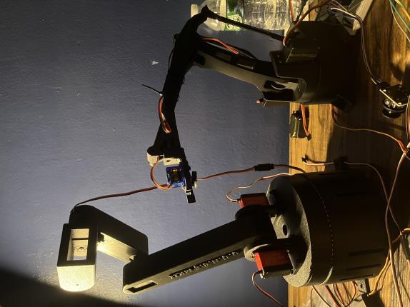
Physical builds of DUNCE MKII on the left and DUNCE MKI on the right, standing on a workbench
02 / From CAD to the workbench · MKII (left), MKI (right)

02 / BACKGROUND

Electrical foundations.
Engineering curiosity.

My background connects electrical construction and maintenance with an electrical engineering education.

I’m pursuing a B.S. in Electrical Engineering at the University at Buffalo, with expected graduation in May 2029. I earned an A.O.S. in Electrical Construction and Maintenance through Alfred State College at Northland Workforce Training Center in May 2025.

UNIVERSITY AT BUFFALO

B.S. Electrical Engineering

Expected May 2029 · GPA 3.92 · Dean’s List

ALFRED STATE · NORTHLAND

A.O.S. Electrical Construction & Maintenance

May 2025 · GPA 4.0 · Summa Cum Laude

TOOLS & CAPABILITIES

Electrical

Circuit analysis · Motor controls · Electrical planning & design · Installation · Troubleshooting

Design & prototyping

Autodesk Fusion · 3D printing · Arduino microcontrollers

Safety training

OSHA 10 certification

03 / FIELD NOTES

Each iteration.
A new challenge.

I build on what I’ve learned, then introduce a new challenge. Each generation of DUNCE is an opportunity to explore another part of engineering.

MKI

Electrical foundations

Power and control system design.

MKII

Mechanical integration

Custom printed parts, gear reductions, and modular end effectors.

MKIII

The next stage PLANNED

Expand electrical and mechanical systems and introduce simulation software.

04 / NEXT CONVERSATION

Let’s talk
engineering. ↗

Interested in my work? Get in touch to start a conversation.